1. PlaneSystem Settings PlaneSystem
1. PlaneSystem Settings PlaneSystem
1.1. Function Description
Before using any interpolation instruction (LINEI/LINEF, ARCI/ARCF, POLYLINE/POLYLINE, BLOCK, etc.), the "* * Plane System Settings * *" must be performed first;
This function is used to create a two axis plane system, and interpolation instructions are implemented based on the plane;
1.2. Instructions for use
The click path for "Flat System Settings" is: Main Menu \ -&# 62; Pulse \ -&# 62; Pulse plane; Plane system settings;
Select the plane number to be created and choose to enable it;
Choose the unit of parameters, which can be millimeters (mm) or pulse PLs. It is recommended that users use mm as the unit, as the parameters are in line with reality and do not require conversion, making them less prone to errors. This unit only controls the parameter units of the setting interface, and the actual motion command units are related to the type of command used;
Out of bounds processing method, corresponding to the set plane boundary. During the use of any interpolation instruction, if the next line segment is about to go out of bounds, corresponding error and processing will be performed. If "do not handle" is selected, the boundary will be ignored. If "slow down and stop" is selected, it will stop at the endpoint of the previous non boundary line segment, which is the starting point of the boundary line segment;
Define the X-axis pulse output port and direction port, Y-axis pulse output port and direction port. Note that the pulse output port must be selected from the corresponding high-speed output port of the PLC, and ordinary output ports cannot be used. The direction output port can be selected arbitrarily. In addition, both the pulse port and direction port can use the D register to modify the corresponding axis number in the program, but the principle must be followed: all enabled planar systems, pulse output ports, and direction output ports cannot be completely duplicated;
Pulse equivalent refers to the distance traveled by the corresponding actuator when a PLC sends a pulse** The intermediate transmission link has been omitted, but in reality, factors such as servo (stepper) motor subdivision, electronic gear ratio, and transmission mechanism transmission ratio need to be considered. Pulse equivalent is the core parameter that connects the set coordinate data with the actual size, and must be accurate. If it is found that the actual size is a scaling of the theoretical size, it is caused by an error in the pulse equivalent setting;
The extreme position is the theoretical boundary position of the planar system, which is set according to the actual situation. If the line segment is about to exceed the boundary, it will be processed according to the selected out of bounds processing method;
Transmission clearance (return clearance) refers to the empty stroke caused by mechanical transmission system wear, installation, etc. when the direction of the transmission shaft changes. The system will compensate for the gap value within several interpolation cycles when the direction of the corresponding axis changes. This parameter may not be set during rough adjustment of the equipment, but should be reasonably set during fine adjustment. Do not set this value too large (maximum value is 5mm). If there is actually a large gap, please adjust the mechanical structure. Additionally, this parameter is not suitable for high-speed operation.
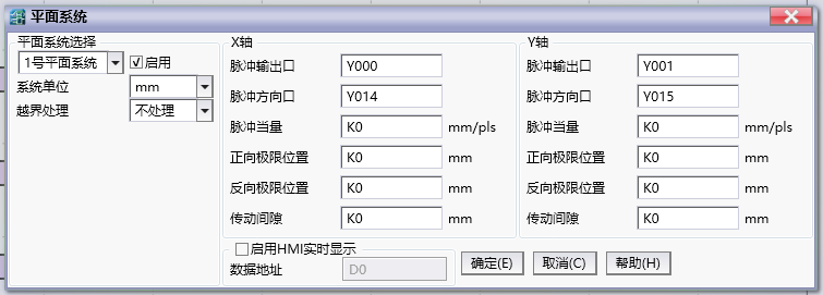
图1 Plane system setting
Attention:
The pulse equivalent of the X-axis and Y-axis should be as similar as possible. If they are not the same, try to choose the system unit as mm to avoid parameter errors caused by conversion;
When the pulse equivalents of the X-axis and Y-axis are different, parameters (such as speed) in the interpolation instruction that are measured in pulses without specifying an axis will be calculated internally based on the X-axis pulse equivalent;
All enabled planar systems, pulse output ports, and directional output ports cannot be completely duplicated;