1. FOLLOW
1. FOLLOW
1.1. Instruction description
This instruction is a pulse sending instruction, whose pulse sending frequency is determined by the speed of the numerical change, and the number of pulses sent is determined by the final size of the numerical change;
The PLC high-speed pulse output port is Y0~Y1 or Y0~Y3, with a pulse frequency range of 0~200KHz.
1.1.1. Instructions for using instructions:
- As shown in the ladder diagram in the example, set the first address of the FOLLOW instruction parameter to D0, the pulse port to Y0, and the direction port to Y12;
In D0 (D1), the target value to be followed is the value of CV235 in this example, but it can also be other values. Note that the rate of change of this value corresponds to the pulse transmission frequency, and the frequency should not exceed the maximum allowable frequency range. In addition, if there is a value in the target value before the FOLLOW instruction is enabled, follow it based on that value. Following is relative, and the initial value before enabling does not affect following.
The D2 parameter is a performance parameter, which can only be set from 1 to 100. When the performance parameters are large, the action strictly follows the changes in the target value with a shorter delay and a higher following stiffness. When the performance parameters are small, the action delay is long and the response is slow, but the following flexibility is good and the response effect to impact is good. The actual action is not strictly followed. If there are no strict requirements for tracking performance, it is recommended to set it to around 50.
The D3 parameter is the feedforward compensation ratio, and the set value can only be between 0 and 100. Due to the lag when following actual motion, if it is necessary to maintain position accuracy during the motion, appropriate feedforward compensation can be used. If the requirement for position accuracy during the process is not high, it is recommended to set it to 0;
Multiply D4 by a coefficient, multiply the change in the following value by the coefficient, and amplify the change in value. Divide D5 by the coefficient, divide the change in the following value by the coefficient, and reduce the change in value. The final result after multiplication and division will be used as the amount of pulses sent. The multiplication and division coefficients can only be set between 1 and 100, and exceeding the extreme value will be treated as an extreme value.
| register | Pulse port |
|---|---|
| M8134 | Y000 |
| M8135 | Y001 |
| M8136 | Y002 |
| M8137 | Y003 |
| register | Pulse port |
|---|---|
| M8138 | Y004 |
| M8139 | Y005 |
| M8140 | Y006 |
| M8141 | Y007 |
| M8142 | Y010 |
| M8143 | Y011 |
| register | Pulse port |
|---|---|
| D8140(D8141) | Y000 |
| D8142(D8143) | Y001 |
| D8144(D8145) | Y002 |
| D8146(D8147) | Y003 |
| register | Pulse port |
|---|---|
| D8148(D8149) | Y004 |
| D8150(D8151) | Y005 |
| D8152(D8153) | Y006 |
| D8154(D8155) | Y007 |
| D8156(D8157) | Y010 |
| D8158(D8159) | Y011 |
1.1.2. Attention:
For high-speed pulse output, it is designed for external high-speed devices. To count the pulses, only the high-speed pulse input counter can be used, and internal counters or Y edge changes cannot be used for counting. When used as a high-speed output, it cannot be used as a regular output port;
The OFF time of transistors has the characteristic of being prolonged under light loads. So, when responsiveness is required, please design a load resistor to increase the load current when the load is lighter;
The pulse accumulation count registers (D8140~D8158) are important registers that can be read and written. When a new value is written, the count will be added or subtracted based on the new value;
Due to the directional output of the pulse in this instruction, the pulse accumulation count registers (D8140~D8158) count according to the direction;
When outputting high-speed pulses, the values in the pulse accumulation count registers (D8140~D8158) are discontinuous and constantly changing. When used for judgment, please use size comparison instead of equal judgment;
When the pulse command is used to output port Y, the Y port cannot be used for other purposes, that is, ordinary commands cannot perform ON or OFF operations on the Y port anymore;
- During the following process, do not experience drastic jumps when following the target value, otherwise the pulse frequency will exceed the maximum frequency limit.
If the frequency of multiple pulse pulses exceeds 200K, a pull-up resistor needs to be added to the pulse output port to ensure that the pulse waveform is not distorted. The pull-up voltage is 24V, and the recommended pull-up resistor is 1K.
FOLLOW Soft Extreme Bottom Layer Usage Instructions
Only the FOLLOW instruction is valid;
Occupy special register M8203, M8204,D8234-D8303, Please do not use them for other functions in the project;
M8203 can be set to 1 to enable the pulse limit mode. Set the corresponding values for D8234 (single character), D8236 (double character), and D8238 (double character), which correspond to the time (ms) for Y000 axis to decelerate and stop beyond the limit, the positive limit position, and the negative limit position. The pulse port parameters will be offset by three double character settings in sequence;
Setting M8204 to 1 can enable the switch signal limit mode. Set the corresponding D8294 (single word) M8205 M8206, which correspond to the time (ms) for Y000 axis out of bounds deceleration stop. Set the positive limit signal (1 when touched, 0 when left) and negative limit signal (1 when touched, 0 when left). Set the pulse port parameters one address later in sequence (the following group is D8295 M8207 M8208);
After the setting is completed, enable FOLLOW. M8203 and M8204 cannot be adjusted again, and further adjustment requires reconnecting the enable. In addition, it is not recommended to enable M8203 and M8204 at the same time (when both are enabled, they will exceed the limit of the priority response pulse number, and both signals will be judged successful when they return to the limit);
Bottom level operation mode:
When the initial position is within the limit range, it responds to the bidirectional signal of the main axis. After exceeding the limit, it decelerates and stops at the set time. Afterwards, it only responds to the input change in the return direction and ignores the input in the away direction until it returns to the limit range;
The criteria for determining boundary crossing are based on the mode, which includes the axis pulse counting (D8140, etc.) crossing the set limit position or the rising edge of the limit signal; The judgment condition for returning within the limit is that the axis pulse count is less than the set limit position, or the falling edge of the limit signal;
When the initial position is outside the limit range, the axis only responds to input changes in the return direction, ignoring input in the away direction until it returns to the limit range.
Special case: When using the switch signal mode, if the FOLLOW is enabled and it is already in the out of range area, and the overall switch signal has been crossed (M8205 and M8206 associated signals are OFF), the initial information is not sufficient to determine the position status, and M8205 or M8206 needs to be manually set to 1.
Attached example program:
When downloading, check the software component initialization option. After power on, it has already been initialized. The spindle is Y000 controlled by EDRVA, and the slave axis is Y001 with FOLLOW command input of D8140 value. Set M8203 to ON, with positive and negative limits set to 60000 and -50000 respectively, and the deceleration stop time set to 100ms; Directly changing the value of D2 to 100000, it can be seen that the spindle moves from 0 to 100000, follows from 0 to 60000, and stops after 100ms of deceleration. Afterwards, the spindle only responds to the returned input; Continue to change D2 to 110000, increase the spindle to 110000, keep the slave shaft stationary, continue to change D2 to 0, return the spindle from 110000 to 0, and move the slave shaft in the opposite direction by 110000.
Turn off M1 disable FOLLOW, set M8203 to 0, set M8204 to 1 to enable switch signal mode, the deceleration time has been initialized to 100ms, and X000 and X001 have been associated as positive and negative limit signals of Y001 port in ladder diagram Network1; By changing the value of D2 to 100000, it can be seen that the spindle moves from 0 to 100000. During this period, if the positive limit signal X000 is triggered or X000 is manually set to 1, the spindle will slow down and stop from the triggering position. Afterwards, it will only respond to changes in the return direction input until the next X000 falling edge is determined to be within the returned limit.
1.2. The valid operands of the instruction
| Input/Output | Data Type | operand | Description |
|---|---|---|---|
| D | 32-bit integer | D | Address |
| OUT | ON/OFF | Y | Pulse |
| DIR | ON/OFF | Y | Direction |
1.3. Example
command table:
NETWORK 000
LD M8151
ENCHT CV235 K2 K0 K99999999
POP
NETWORK 001
LD M0
MOVD CV235 D0
MOV K20 D2
MOV K0 D3
MOV K1 D4
MOV K1 D5
FOLLOW D0 Y000 Y012
POP
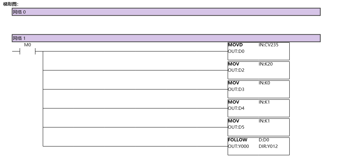
图1 FOLLOW11
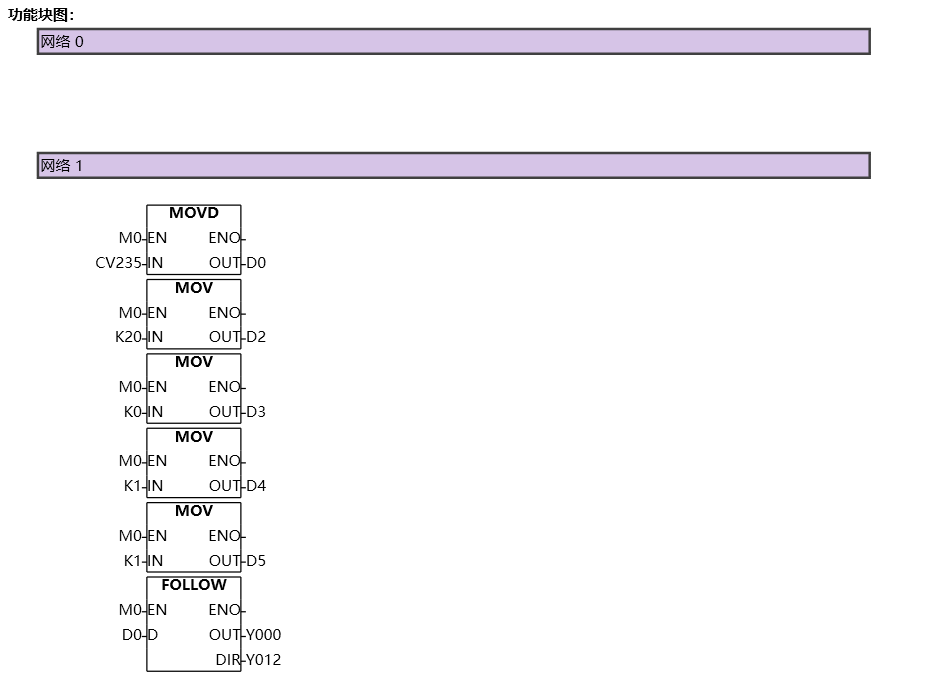
图2 FOLLOW12