1. Multi segment pulse positioning output TBL
1. Multi segment pulse positioning output TBL
1.1. Instruction Description
Y0~Y1 or Y0~Y3 are high-speed pulse output ports;
For the FAs series PLC, single pulse: the instruction can output a frequency range of 0Hz~200KHz, a pulse quantity range of K0~K2147483647, and stop outputting when the frequency is 0;
For relay type PLCs, they do not have high-speed pulse function, and the maximum output frequency of all output ports is determined by the closing time of the relay;
The function of this instruction is to output a specified number of pulses at a certain frequency. When starting, it accelerates uniformly from 1000Hz to a fixed speed and outputs at a constant speed. When ending, it decelerates from a fixed speed to 0, completing a segment of pulse output;
It is legal for the number of pulses and acceleration/deceleration time to satisfy the following relationship:
(Starting frequency Hz+Ending frequency Hz) × (Acceleration/Deceleration time ms ÷ 1000)<=Number of pulses × 2
Function: Conditional position control.
Usage description: As shown in the figure below, the starting address of the data is used to store the frequency and pulse values of each segment. After M200 is turned on, the instruction is enabled, and the data will be transferred to the D register. The "current pulse segment" is 1, but the pulse will not be sent immediately. The first segment of the pulse needs to wait for the start condition M500 to be turned on before starting to send it. The data in the D register can be modified in the program, and it will automatically retrieve the value from the D register when running to that segment. Before each pulse is sent, there is a waiting event and execution condition, which consists of a wait signal, ATC time, and completion of pulse transmission. In the first paragraph of the figure, the wait signal is M500. Only when the current paragraph to be executed is the first paragraph, M500 is turned on to start sending the first paragraph. After the end, the end identification bit M501 is turned on, and the execution condition M500 is disconnected. The "current pulse segment" is the paragraph number for "jump to". After the first paragraph is executed, jump to the next paragraph. "Jump to" can be filled in any set paragraph, as shown in Figure 2. The waiting event for the second segment is the ATC time, which is set as K2000 units of milliseconds in the execution conditions. It can also be set as a D register and starts timing from the end of the first segment. After 2000ms, the second segment will start running, and the end flag of the first segment M501 will be disconnected when the second segment starts running. Connect M503 after the second paragraph ends. The third waiting event is the completion of pulse transmission, which means that once the second pulse transmission is completed, it immediately enters the third pulse transmission and immediately disconnects M503. After the third paragraph runs, it jumps to the fourth paragraph, which is similar to the first paragraph. After the fourth section finishes running, jump to the first section to form a loop.
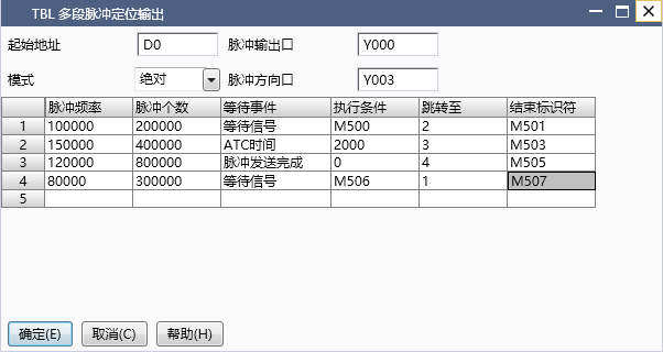
图1 TBL
| register | Pulse port |
|---|---|
| M8134 | Y000 |
| M8135 | Y001 |
| M8136 | Y002 |
| M8137 | Y003 |
| register | Pulse port |
|---|---|
| M8138 | Y004 |
| M8139 | Y005 |
| M8140 | Y006 |
| M8141 | Y007 |
| M8142 | Y010 |
| M8143 | Y011 |
| register | Pulse port |
|---|---|
| D8140(D8141) | Y000 |
| D8142(D8143) | Y001 |
| D8144(D8145) | Y002 |
| D8146(D8147) | Y003 |
| register | Pulse port |
|---|---|
| D8148(D8149) | Y004 |
| D8150(D8151) | Y005 |
| D8152(D8153) | Y006 |
| D8154(D8155) | Y007 |
| D8156(D8157) | Y010 |
| D8158(D8159) | Y011 |
| register | Pulse port |
|---|---|
| D8092 | Y000 |
| D8093 | Y001 |
| D8094 | Y002 |
| D8095 | Y003 |
| register | Pulse port |
|---|---|
| D8096 | Y004 |
| D8097 | Y005 |
| D8098 | Y006 |
| D8099 | Y007 |
| D8100 | Y010 |
| D8101 | Y011 |
| register | Pulse port |
|---|---|
| D8124 | Y000 |
| D8125 | Y001 |
| D8126 | Y002 |
| D8127 | Y003 |
| register | Pulse port |
|---|---|
| D8128 | Y004 |
| D8129 | Y005 |
| D8130 | Y006 |
| D8131 | Y007 |
| D8132 | Y010 |
| D8133 | Y011 |
1.1.1. Attention:
For high-speed pulse output, it is designed for external high-speed devices. To count the pulses, only the high-speed pulse input counter can be used, and internal counters or Y edge changes cannot be used for counting. When used as a high-speed output, it cannot be used as a regular output port;
The OFF time of transistors has the characteristic of being prolonged under light loads. So, when responsiveness is required, please design a load resistor to increase the load current when the load is lighter;
For the pulse output Y0, the number of pulses is accumulated in register D8140 (D8141), where D8141 stores the high 16 bits and D8140 stores the low 16 bits;
The pulse accumulation count registers (D8140~D8146) are important registers that can be read and written. When a new value is written, the count will be added or subtracted based on the new value;
Due to the directional output of the pulse in this instruction, the pulse accumulation counting registers (D8140~D8146) count according to the direction;
When outputting high-speed pulses, the values in the pulse accumulation count registers (D8140~D8146) are discontinuous and constantly changing. When used for judgment, please use size comparison instead of equal judgment;
When the waiting event is the completion of pulse transmission, the execution condition does not need to be filled in and defaults to K0;
The "relative" and "absolute" in "mode" refer to whether the number of pulses filled in is in relative or absolute coordinates;
'Jump to' can be set to any set paragraph, and it will eventually form a loop;
The number of pulses and frequency cannot be input as zero. If the input parameters do not meet the acceleration legality requirements, the system will readjust the speed curve.
If the frequency of multiple pulse pulses exceeds 200K, a pull-up resistor needs to be added to the pulse output port to ensure that the pulse waveform is not distorted. The pull-up voltage is 24V, and the recommended pull-up resistor is 1K.
1.2. The valid operands of the instruction
| Input/Output | Data Type | operand | Description |
|---|---|---|---|
| D | 32-bit integer | D | Address |
| OUT | ON/OFF | Y | Pulse |
| DIR | ON/OFF | Y | Direction |
1.3. Example
Command table:
NETWORK 000
LD M200
MPS
MEP
MOV K100 D8092//Y000's acceleration and deceleration time is set to 100ms
MOV K100 D8093//Y001's acceleration and deceleration time is set to 100ms
MPP
TBL D0 Y000 Y005
TBL D100 Y001 Y006
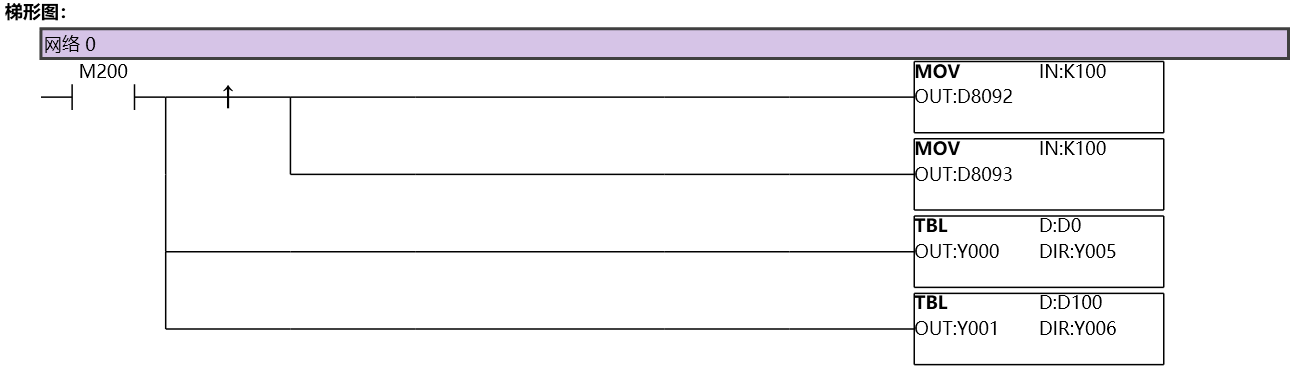
图2 TBL11
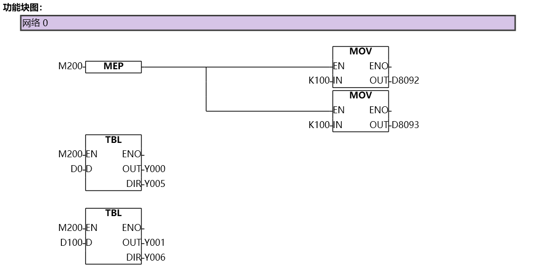
图3 TBL12