1. Return to the origin at any point ZRNR
1. Return to the origin at any point ZRNR
1.1. Instruction Description
When the input terminal is turned on, the zero return command ZRNR at any point will stop sending pulses after running to a specific side of the specified zero signal range based on the current position of the workbench and the selected default zero return direction and mode. When the input terminal is turned off, pulse transmission stops.
| register | Pulse port |
|---|---|
| M8134 | Y000 |
| M8135 | Y001 |
| M8136 | Y002 |
| M8137 | Y003 |
| register | Pulse port |
|---|---|
| M8138 | Y004 |
| M8139 | Y005 |
| M8140 | Y006 |
| M8141 | Y007 |
| M8142 | Y010 |
| M8143 | Y011 |
| register | Pulse port |
|---|---|
| D8140(D8141) | Y000 |
| D8142(D8143) | Y001 |
| D8144(D8145) | Y002 |
| D8146(D8147) | Y003 |
| register | Pulse port |
|---|---|
| D8148(D8149) | Y004 |
| D8150(D8151) | Y005 |
| D8152(D8153) | Y006 |
| D8154(D8155) | Y007 |
| D8156(D8157) | Y010 |
| D8158(D8159) | Y011 |
1.1.1. Explanation of Instruction Parameters
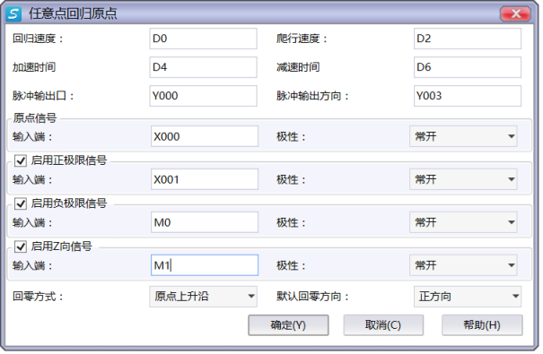
图1 ZRNR Instruction Parameter Editing Window
The parameter types for crawling speed and regression speed can be D/K/H, both of which are 32-bit. Inputting negative values for both speeds is equivalent to changing the default zeroing direction, but note that this will change the position of the zero signal;
Set the pulse output port Y and the pulse direction output port Y;
The origin signal input terminal is connected to the corresponding origin sensor and the positive and negative limit signal input terminals, and the signal output of the positive and negative limit sensors (the signal input port can be selected as X port or M register), where the positive and negative limits and z-phase signals are optional;
The polarity of the origin signal and the positive and negative limit signals is selected based on the actual polarity of the sensor signal used (normally open or normally closed);
The default zeroing direction determines the movement direction of the worktable from the initial position to zero in most cases (except when it is within the limit signal);
The zero return mode is divided into two modes: near point signal and origin rising edge. The two modes have different paths and specific positions when returning to zero (see the introduction of zero return path for details);
The return to zero mode and the default return to zero direction jointly determine the position of the zero signal (on which side of the zero signal range);
Before using the ZRNR instruction, it is necessary to confirm the following aspects in sequence (refer to the precautions for specific methods):
-Confirm the positive and negative directions as well as the position of the positive and negative limits;
-Confirm the default zeroing direction based on the actual situation;
-Choose the appropriate zeroing mode;
-Determine the position of the zero signal based on the selected default zeroing direction and zeroing mode;
1.1.2. Attention
After completing the return to origin action with this instruction, the pulse accumulation registers (D8140~D8147) of the corresponding output ports will automatically reset to zero, serving as the origin;
When the pulse command is used to output port Y, the Y port cannot be used for other purposes, that is, ordinary commands cannot perform ON or OFF operations on the Y port anymore;
The filtering mode of the X port connected to each sensor should be set to inactive, otherwise the endpoint position will cause significant deviation. When using the high-speed input port for the Z-phase signal, the detection line is about 100 microseconds, and when using the non high-speed port, it is detected during the scanning cycle;
Positive direction and positive limit: When the pulse direction port is at high level, the direction of the worktable movement (motor rotation) is positive, and the corresponding limit position is positive limit; On the contrary, it is in the negative direction and has a negative limit;
During the zeroing process, the output of the pulse direction port is automatically controlled by the PLC based on the position of the workbench, without the need for user control (ensuring that the pulse direction port is not affected by other instructions);
If the default zero return direction is selected as the positive direction, in most cases (except when the initial position is within the limit signal), the pulse direction port output is high when returning to zero, and the worktable moves forward; If the negative direction is chosen, the situation is completely opposite. Users can choose the appropriate default zeroing direction based on their actual situation (for example, considering the area where the initial position of the workbench zeroing starts);
As shown in the following figure, users need to clarify the position of the zero point before use:
-Near point signal mode: If the default zero return direction is selected as the positive direction, the final zero point position will be the edge of the origin sensor signal range close to the positive limit; If the negative direction is selected, the final zero point position is the edge of the origin sensor signal range close to the negative limit.
-Origin rising edge mode: If the default zero return direction is selected as the positive direction, the final zero position will be the edge of the origin sensor signal range close to the negative limit; If the negative direction is selected, the final zero point position is the edge of the origin sensor signal range close to the positive limit.
1.1.3. The final zero position in the near point signal mode::
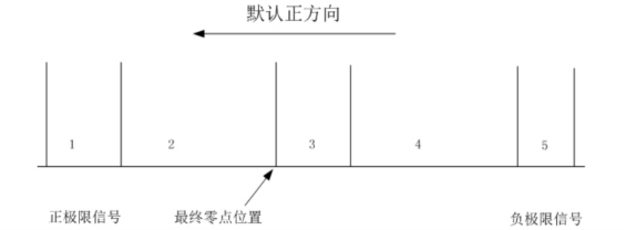
图2 Default positive direction
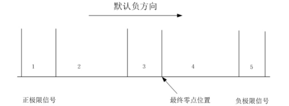
图3 Default Negative Direction
1.1.4. The final zero position in the rising edge mode at the origin:
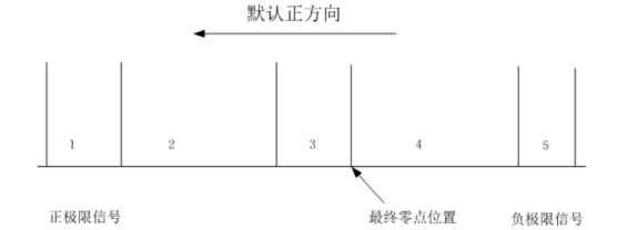
图4 Default positive direction
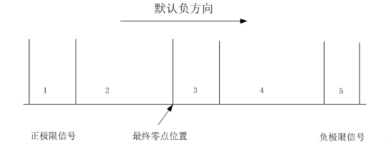
图5 Default Negative Direction
1.1.5. Regarding the positive and negative limit signals
Both the positive and negative limit signals and the Z signal are optional. If the positive and negative limit signals or one of them is not selected, it is not possible to achieve any point return to zero (the following return to zero paths that involve unchecked limit signals cannot be achieved, while the rest of the paths that do not involve unchecked signals can still be achieved). Users can choose the Z-phase signal according to their needs (the Z-phase pulse on the servo can be connected to the PLC, but it must be a 24V signal, otherwise the PLC cannot recognize it).
If the workbench stops moving after entering the positive and negative limits during the zeroing process and reports an error: the origin signal is lost, please check if the origin sensor signal is invalid. After confirming the troubleshooting, the reset command can still be reset to zero. If the workbench stops during the zeroing process and reports an error: the acceleration and deceleration distance is too long, it indicates that the origin rising edge mode encountered the limit signal during deceleration to 0 or the workbench completely exceeded the limit signal. At this time, please check the position of the workbench and reduce the acceleration and deceleration time.
If the workbench cannot slow down to crawling speed within the origin sensor, please widen the signal range of the origin sensor or reduce the acceleration and deceleration time appropriately, so that the workbench can slow down to crawling speed.
To ensure safety, please ensure that the positive and negative limits have sufficient width to slow down the worktable to 0 within its signal. Otherwise, exceeding the worktable limit will cause an error message stating that the acceleration and deceleration distance is too long.
To ensure safety, it is recommended to choose the polarity of the positive and negative limit signals as normally closed (to prevent accidents caused by the failure of the positive and negative limits).
1.2. The valid operands of the instruction
| Input/Output | Data Type | operand | Description |
|---|---|---|---|
| HV | 32-bit integer | D/CV/K/H/FD, bit composite word (X/Y/M/C/T/S), local variable (LD) | regression speed |
| LV | 32-bit integer | D/CV/K/H/FD, bit composite word (X/Y/M/C/T/S), local variable (LD) | crawling speed |
| AC | 16 bit unsigned integer | D/CV/TV/AI/AO/K/H/V/Z/FD, bit composite word (X/Y/M/C/T/S), local variable (LW) | acceleration time |
| DC | 16 bit unsigned integer | D/CV/TV/AI/AO/K/H/V/Z/FD, bit composite word (X/Y/M/C/T/S), local variable (LW) | deceleration time |
| OUT | ON/OFF | Y | Pulse |
| DIR | ON/OFF | Y | Direction |
1.3. Example
Command table:
NETWORK 000
LD M20
MOVD K10000 D0
MOVD K5000 D2
ZRNR D0 D2 K200 K200 Y000 Y002
POP
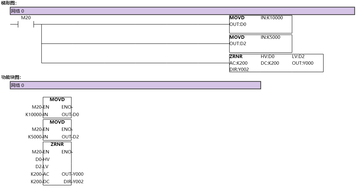
图6 ZRNR
1.4. Return to Zero Diagram:
Taking the default zeroing direction as negative as an example, explain the zeroing paths in two different modes when the workbench is at any position between the positive and negative limits:
1.4.1. a) The initial position is located between the positive limit and the origin signal
1.4.1.1. Near point signal mode
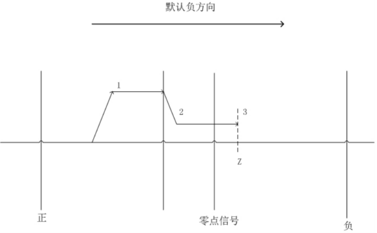
图7 Near Point Signal Mode
1.4.1.2. As shown in the above figure:
Accelerate the workbench in the negative direction to the return speed;
After entering the origin signal, it begins to decelerate in the negative direction to reach the crawling speed;
Stop when reaching the zero signal side, and if the Z-phase signal is selected, stop at the Z-phase signal;
1.4.1.3. Origin rising edge mode
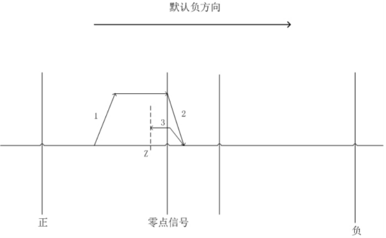
图8 Origin rising edge mode
1.4.1.4. As shown in the above figure:
Accelerate the workbench in the negative direction to the return speed;
After entering the origin signal, it begins to decelerate in the negative direction to 0;
Reverse acceleration to crawling speed;
Stop when reaching the zero signal side, and if the Z-phase signal is selected, stop at the Z-phase signal;
1.4.2. b) The initial position is within the positive limit signal
1.4.2.1. Near point signal mode
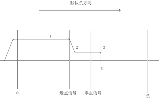
图9 Near point signal mode
1.4.2.2. As shown in the above figure:
Accelerate the workbench in the negative direction to the return speed;
After entering the origin signal, it begins to decelerate in the negative direction to reach the crawling speed;
Stop when reaching the zero signal side, and if the Z-phase signal is selected, stop at the Z-phase signal;
1.4.2.3. Origin rising edge mode
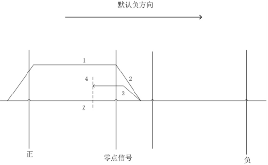
图10 Origin rising edge mode
1.4.2.4. As shown in the above figure:
Accelerate the workbench in the negative direction to the return speed;
After entering the origin signal, it begins to decelerate in the negative direction to 0;
Reverse acceleration to crawling speed;
Stop when reaching the zero signal side, and if the Z-phase signal is selected, stop at the Z-phase signal;
1.4.3. c) The initial position is located inside the origin signal
1.4.3.1. Near point signal mode
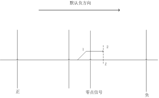
图11 Near point signal mode
1.4.3.2. As shown in the above figure:
Accelerate the workbench in the negative direction to crawling speed;
Stop when reaching the zero signal side, and if the Z-phase signal is selected, stop at the Z-phase signal;
1.4.3.3. Origin rising edge mode
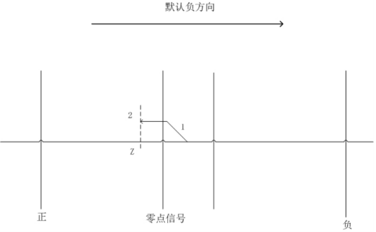
图12 Origin rising edge mode
1.4.3.4. As shown in the above figure:
Accelerate the workbench in the positive direction to crawling speed;
Stop when reaching the zero signal side, and if the Z-phase signal is selected, stop at the Z-phase signal;
1.4.4. d) The initial position is located between the origin signal and the negative limit
1.4.4.1. Near point signal mode
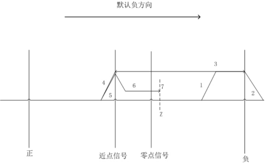
图13 Near point signal mode
1.4.4.2. As shown in the above figure:
Accelerate the workbench in the negative direction to the return speed;
When entering the negative limit signal, immediately decelerate to 0;
Immediately start accelerating in the positive direction to the return speed after slowing down to 0;
When leaving the range of the origin signal, immediately begin to decelerate in the positive direction to 0;
Immediately start accelerating in the negative direction to the return speed after slowing down to 0;
When entering the origin signal range, immediately begin to decelerate in the negative direction to the crawling speed;
Stop when reaching the zero signal side, and if the Z-phase signal is selected, stop at the Z-phase signal;
1.4.4.3. Origin rising edge mode
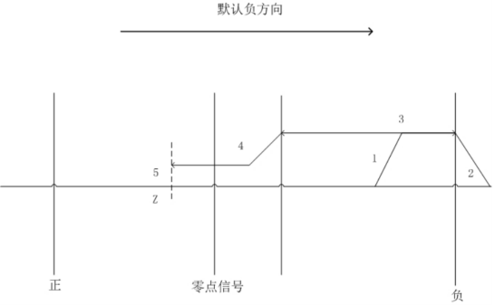
图14 Origin rising edge mode
1.4.4.4. As shown in the above figure:
Accelerate the workbench in the negative direction to the return speed;
When entering the negative limit signal, immediately decelerate to 0;
Immediately start accelerating in the positive direction to the return speed after slowing down to 0;
When entering the origin signal range, immediately begin to decelerate in the positive direction to the crawling speed;
Stop when reaching the zero signal side, and if the Z-phase signal is selected, stop at the Z-phase signal;
1.4.5. e) The initial position is within the negative limit signal
1.4.5.1. Near point signal mode
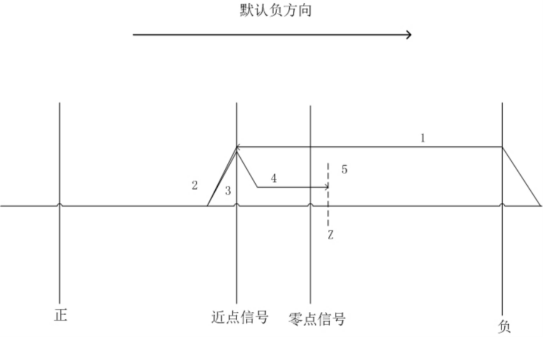
图15 Near point signal mode
1.4.5.2. As shown in the above figure:
Accelerate the workbench in the positive direction to the return speed;
When leaving the range of the origin signal, immediately begin to decelerate in the positive direction to 0;
Immediately start accelerating in the negative direction to the return speed after slowing down to 0;
When entering the origin signal range, immediately begin to decelerate in the negative direction to the crawling speed;
Stop when reaching the zero signal side, and if the Z-phase signal is selected, stop at the Z-phase signal;
1.4.5.3. Origin rising edge mode

图16 Origin rising edge mode
1.4.5.4. As shown in the above figure::
When entering the origin signal range, immediately begin to decelerate in the positive direction to the crawling speed;
Stop when reaching the zero signal side, and if the Z-phase signal is selected, stop at the Z-phase signal;
1.4.6. Zero return error analysis:
The operating speed at the final zero position (the smaller the speed, the smaller the deviation);
The length of the PLC scanning cycle (the shorter the scanning cycle, the smaller the deviation);
The magnitude of the motion inertia of the moving part (the smaller the motion inertia, the smaller the deviation);